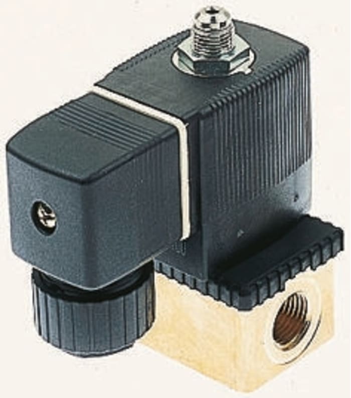
Elektromagnetický ventil 134160 3portový NC 24 V DC, 1/8in Burkert

Technické dokumenty
Špecifikácie
Brand
BurkertNapájecí napětí
24 V dc
Počet portů
3
Velikost připojení
1/8in
Připojení
1/8" G vnitřní
Obsluha
Direct
Výchozí poloha ventilu
NC
Vhodné využití
Gas, Liquid
Typ
3/2
Průměr vstupního otvoru
1.2mm
Gehäusematerial
Brass
Řada
6012
Maximální pracovní tlak
10 barů
Rozsah provozních teplot
Maximálně +55 °C
Standard závitu nebo typ přípojky
G
Maximální provozní teplota
+55°C
Pohlaví spojení
Female
Maximální doba uzavření
9ms
Součinitel proudění Kv
0.045m³/h
Maximální doba otevření
7ms
Krajina pôvodu
Germany
Podrobnosti o výrobku
3 // 2 NF přímé ovládání, miniaturní elektromagnetické ventily, řada 6012
Rozsah miniaturních, modulárních, přímo řízených elektromagnetických ventilů pro neutrální kapaliny do +100 °C.
Funkce 3 // 2 NF, DL výstup, s výfukem při vypnutém stavu.
Schopen vyměnit elektromagnet bez demontáže ventilu.
Elektromagnet lze umístit volně nebo zablokovat ve 4 polohách v intervalech 90°.
Standardně vysoce kvalitní těsnicí materiál FPM (Viton).
Konektor DIN 43 650C.
Těleso vyrobené z mosazi.
3 Way Inert Gases and Fluid Valves
Compact solenoid valves suitable for most gas and fluid handling applications. Where practical, valves are shown with a schematic diagram showing the (circuit) function. The diagram is laid out so that the left hand side of the diagram describes the valves operation when the coil is energised. When the coil is de-energised, the spring (or servo-assist) return controls the valve and this is described on the right hand side of the diagram, see the typical schematic diagram below.,The 3//2-way designation indicates a valve with three ports and two modes of operation. It is normal practice to refer to 2//2-way valves as two-way.,The port designations A, B, P, P1, P2 and R are used on the schematic diagrams and are marked on the valve bodies. Valve bodies are marked for a specific circuit function but can often be used for other functions. Reference to the schematic diagrams and technical specifications will indicate the appropriate connections and pressure capabilities should an alternative circuit function be required.
P.O.A.
1
P.O.A.
Informácie o zásobách sú dočasne nedostupné.
1
Informácie o zásobách sú dočasne nedostupné.
Technické dokumenty
Špecifikácie
Brand
BurkertNapájecí napětí
24 V dc
Počet portů
3
Velikost připojení
1/8in
Připojení
1/8" G vnitřní
Obsluha
Direct
Výchozí poloha ventilu
NC
Vhodné využití
Gas, Liquid
Typ
3/2
Průměr vstupního otvoru
1.2mm
Gehäusematerial
Brass
Řada
6012
Maximální pracovní tlak
10 barů
Rozsah provozních teplot
Maximálně +55 °C
Standard závitu nebo typ přípojky
G
Maximální provozní teplota
+55°C
Pohlaví spojení
Female
Maximální doba uzavření
9ms
Součinitel proudění Kv
0.045m³/h
Maximální doba otevření
7ms
Krajina pôvodu
Germany
Podrobnosti o výrobku
3 // 2 NF přímé ovládání, miniaturní elektromagnetické ventily, řada 6012
Rozsah miniaturních, modulárních, přímo řízených elektromagnetických ventilů pro neutrální kapaliny do +100 °C.
Funkce 3 // 2 NF, DL výstup, s výfukem při vypnutém stavu.
Schopen vyměnit elektromagnet bez demontáže ventilu.
Elektromagnet lze umístit volně nebo zablokovat ve 4 polohách v intervalech 90°.
Standardně vysoce kvalitní těsnicí materiál FPM (Viton).
Konektor DIN 43 650C.
Těleso vyrobené z mosazi.
3 Way Inert Gases and Fluid Valves
Compact solenoid valves suitable for most gas and fluid handling applications. Where practical, valves are shown with a schematic diagram showing the (circuit) function. The diagram is laid out so that the left hand side of the diagram describes the valves operation when the coil is energised. When the coil is de-energised, the spring (or servo-assist) return controls the valve and this is described on the right hand side of the diagram, see the typical schematic diagram below.,The 3//2-way designation indicates a valve with three ports and two modes of operation. It is normal practice to refer to 2//2-way valves as two-way.,The port designations A, B, P, P1, P2 and R are used on the schematic diagrams and are marked on the valve bodies. Valve bodies are marked for a specific circuit function but can often be used for other functions. Reference to the schematic diagrams and technical specifications will indicate the appropriate connections and pressure capabilities should an alternative circuit function be required.